Call Support 24/7
+86-28-68724242

product
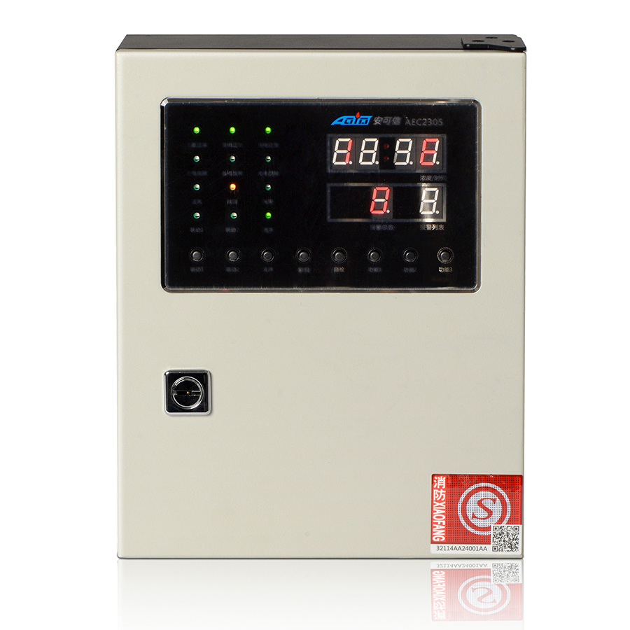
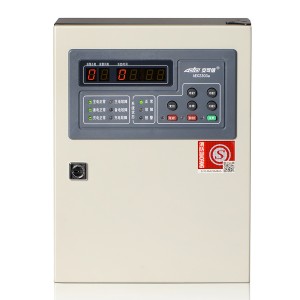
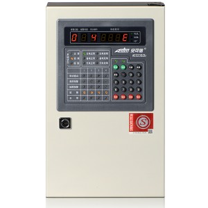
AEC2305 Small Capacity Gas Alarm Controller
Technical Specifications
| Operating voltage | AC176V~AC264V (50Hz±1%) |
| Power consumption | ≤10W (excluding supporting equipment) |
| Environmental condition for operating | temperature 0℃~+40℃, relative humidity≤93%RH |
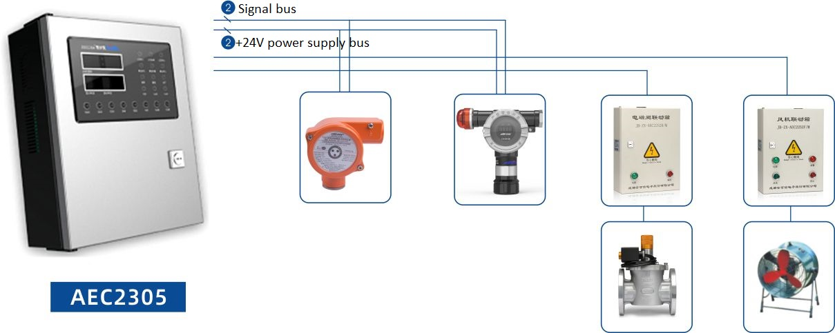
| Signal transmission | four-bus system (S1, S2, +24V and GND) |
| Signal transmission distance | ≤1500m (2.5mm2) |
| Types of gas detected | %LEL |
| Capacity | 1~2 |
| Adaptive equipment | gas detectors :GT-AEC2331a, GT-AEC2232a,GT-AEC2232bX/A |
| Input module | JB-MK-AEC2241 (d) |
| Fan linkage boxes | JB-ZX-AEC2252F |
| Solenoid valve linkage boxes | JB-ZX-AEC2252B |
| Output | two sets of programmable relay outputs, with the contact capacity of 10A/DC30V or 10A/AC250V |
| RS485Bus communication interface (standard MODBUS protocol)Alarm setting | low alarm and high alarm |
| Alarming mode | audible-visual alarm |
| Indication error | ±5%LEL |
| Display mode | nixie tube |
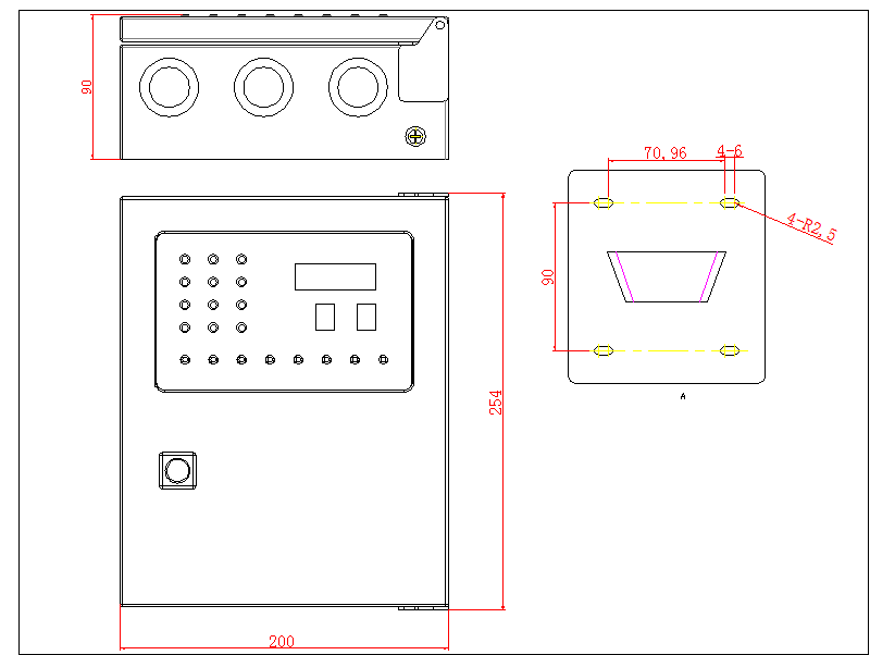
| Boundary dimensions( length ×width ×thickness) | 254mm×200mm×90mm |
| Gross weight | about 4.5kg (including standby power supply) |
| Mounting mode | wall-mounted |
| Standby power supply | DC12V /1.3Ah×2 |
| Mounting mode | wall-mounted |
| Standby power supply | DC12V /1.3Ah ×2 |
Major Features
● Bus signal transmission (S1, S2, GND and +24V);
● Switchable real-time concentration display or time display, for monitoring of combustible gases and steams;
● Automatic calibration, and automatic tracing of sensor ageing;
● Anti-RFI/EMI interference;
● Two alarming levels: Low alarm and high alarm, with the alarm values adjustable;
● Processing of alarm signals has priority over processing of failure signals;
● Automatically monitoring failure; correctly showing the failure location and type;
● Two sets of programmable internal linkage output modules and two programmable emergency buttons to automatically or manually control external equipment;
● Strong memory: historical records of the latest 999 alarming records, 100 failure records and 100 startup/shutdown records, which will not be lost in case of power failure;
● RS485 bus communication interface is available for matching any equipment with standard MBODBUS protocol, thus to form a larger gas network management system;
● Simple and convenient operation: all configurations of the system can be completed by one button;
● Beautiful appearance, small volume and convenient installation.
Structure
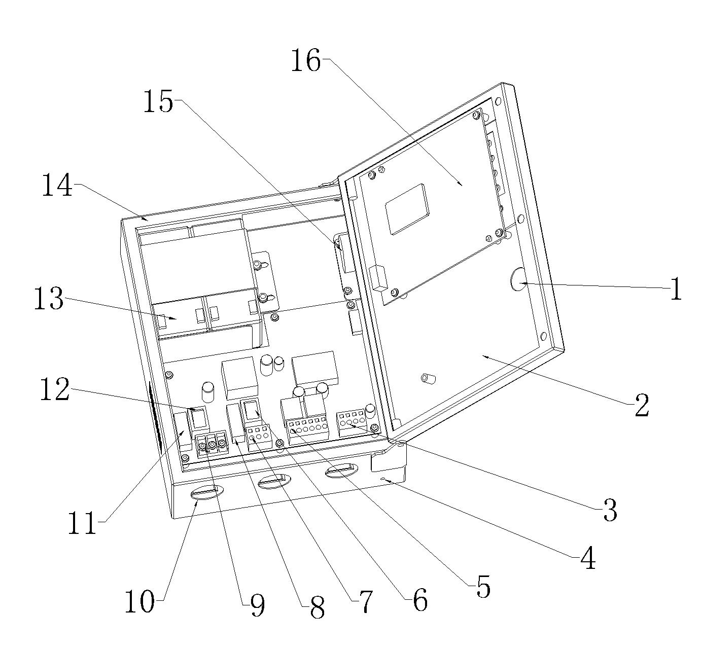
1. Side lock
2. Cover
3. Bus connection terminal
4. Grounding terminal
5. Connection terminals of internal output modules
6. Switch of standby power supply
7. RS485 bus communication interface
8. Fuse of standby power supply
9. Power supply terminal
10. Incoming hole
11. Fuse of main power supply
12. Switch of main power supply
13. Standby power supply
14. Bottom box
15. Horn
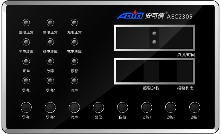
16. Control panel
Control panel / Dimensional diagram for the bottom board and the casing
Wiring Diagram

Connection terminals:
L, and N: AC220V power supply terminals
NC (normally closed), COM (Common) and NO (normally open): (2 sets) output terminals for relay external control signals output terminals
S1, S2, GND, + 24V: System bus connection terminal
A, GND and B: RS485 communication interface connection terminals
1) Capacity: the total number of detectors and input modules externally connected to the controller shall be not more than 2.
2) In order to control external equipment, there are contact outputs for two sets of relays (namely, internal linkage modules) inside the controller.
The system default setting is that the two sets of relays will output signals whenever a detector gives an alarm.
3) Two sets of internal linkage modules can provide one of the following five output modes:
A. Passive switching value signal output: contact capacity: 10A/AC220V or 10A/DC24V
B. Passive jogging signal output: contact capacity: 10A/AC220V or 10A/DC24V
C. DC24V/200mA level signal output (NO+, COM-)
D. DC24V/200mA impulse signal output (NO+, COM-)
E. Capacitance output (NO+, COM-)
Special note:
Default: “Output 1” and “Output 2”are passive switching value signals.

