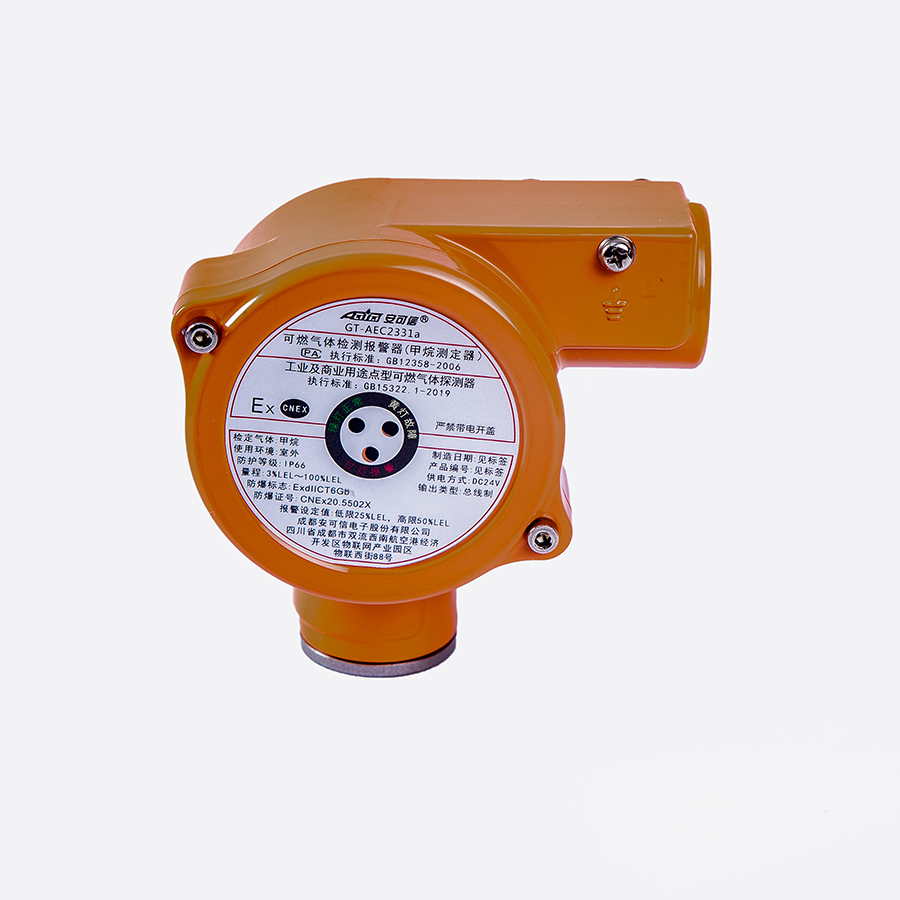
product
Professional China Combustible Gas Detection Controller - AEC2301a A-Bus signal Gas Leak Alarm Controller – Action
Professional China Combustible Gas Detection Controller - AEC2301a A-Bus signal Gas Leak Alarm Controller – Action Detail:
Technical Specifications
| Operating voltage | AC176V~AC264V (50Hz±1%) |
| Power consumption | ≤15W (excluding supporting equipment) |
| Environmental condition for operating | temperature-10℃~+50℃, relative humidity≤93%RH |
| Signal transmission | four-bus system (S1, S2, +24V and GND) |
| Signal transmission distance | 1500m (2.5mm2) |
| Types of gas detected | %LEL, ppm and %VOL |
| Capacity | four sets of bus loops (capacity of each loop≤64 points), total capacity≤256 points (including detectors and input/output modules) |
| Adaptive equipment | gas detectors:GT-AEC2331a, GT-AEC2232a, GT-AEC2232bX/A, GQ-AEC2232bX/A |
| Input module | JB-MK-AEC2241 (d) |
| Output module | JB-MK-AEC2242 (d) |
| Fan linkage boxes | JB-ZX-AEC2252F and JB-ZX-AEC2252F/M |
| Solenoid valve linkage boxes | JB-ZX-AEC2252B and JB-ZX-AEC2252B/M |
| Output | four sets of relay contact signals, with the capacity of 3A/DC24V or 1A/AC220V RS485 bus communication interface (standard MODBUS protocol) |
| Alarm setting | low alarm and high alarm |
| Alarming mode | audible-visual alarm |
| Display | true color 7” widescreen LCD Chinese display |
| Boundary dimensions(length ×width ×thickness) | 520mm×400mm×127mm |
| Mounting mode | wall-mounted |
| Standby power supply | DC12V /7Ah ×2 |
| Optional equipment | Printer AEC-PRT |
Major Features
● Four sets of bus loop transmission, 256 monitoring points, strong system anti-interference capability, partition management, cost-efficient wiring, convenient and efficient installation;
● 7 “high resolution true color LCD, similar to windows operating system, convenient and efficient menu operation, real-time one screen display of alarm information, failure information, concentrations at detectors, etc., types of gases shown in Chinese, free setting of alarm positions, convenient system query and maintenance;
● Free setting of two level alarm values and three alarming types (rising/falling/two-level) to improve system monitoring function;
● Strong memory: historical records of the latest 1,000 failure records, 1,000 alarming records and 100 startup/shutdown records, which will not be lost in case of power failure;
● Automatically monitoring failure; correctly showing the failure location and type; shielding (or isolating) any detector or module according to the user’s choice, convenient for on-line system maintenance;
● Strong logic programming and free configurations of output modules can realized remote automatic control over various kinds of external equipment; eight programmable emergency buttons can manually output control signals;
● Manually/automatically printing and adding real-time data records;
● Setting operating authorities for various users to realize level-based management and avoid misoperation;
● RS485 bus communication (standard MODBUS protocol) interface to realize communication with the host control system and networking with the fire and gas network system, to improve system integration.
Structure
1. Side lock
2. Printer (optional)
3. Cover
4. Horn
5. Relay connection terminal
6. RS485 bus communication interface
7. Bottom box
8. Bus connection terminal
10. Switch of main power supply
11. Grounding terminal
12. Power supply terminal
13. Switch of standby power supply
14. Switch power supply
15. Standby power supply
16. LCD control panel
17. Control panel box

Panel Marks And Mounting Instructions
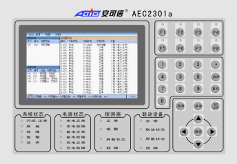

● Make 4 mounting holes (hole depth: ≥40mm) in a wall as per the requirements for bottom board mounting holes (hole symbols 1-4);
● Insert a plastic expansion bolt into each mounting hole;
● Fix the bottom board onto the wall, and fasten it onto the expansion bolts with 4 self-tapping screws (ST3.5×32);
● Hang the welding hanging parts on the back of the controller onto location A at the bottom board to complete mounting of the controller.
Panel Marks And Mounting Instructions
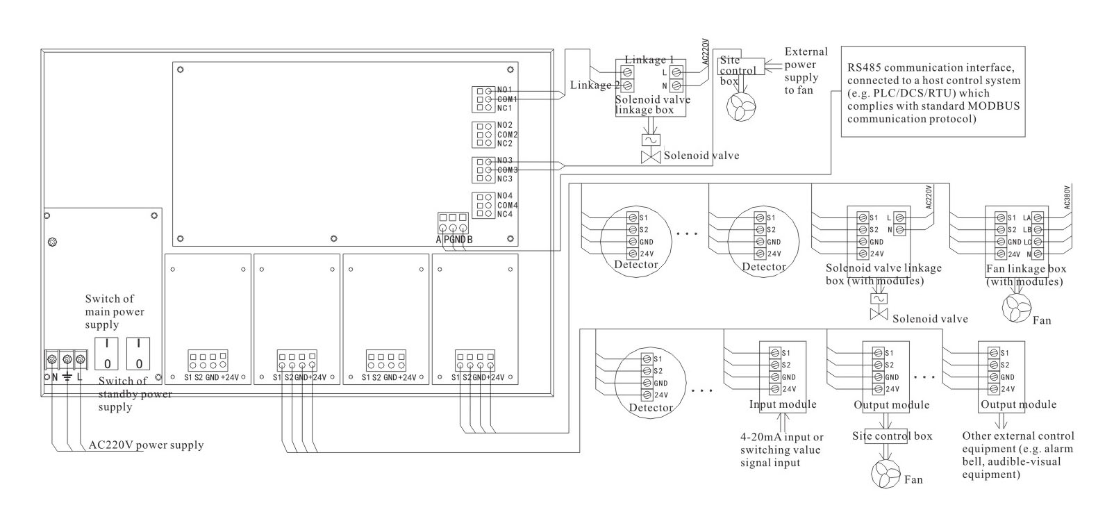
N, and L: AC220V power supply terminals
NO (normally open), COM (common) and NC (normally closed): (4 sets) output terminals for relay external control signals output terminals
S1, S2, GND and +24V: (4 sets) bus connection terminals (≤64 points for each set)
A, GND and B: RS485 communication interface connection terminals
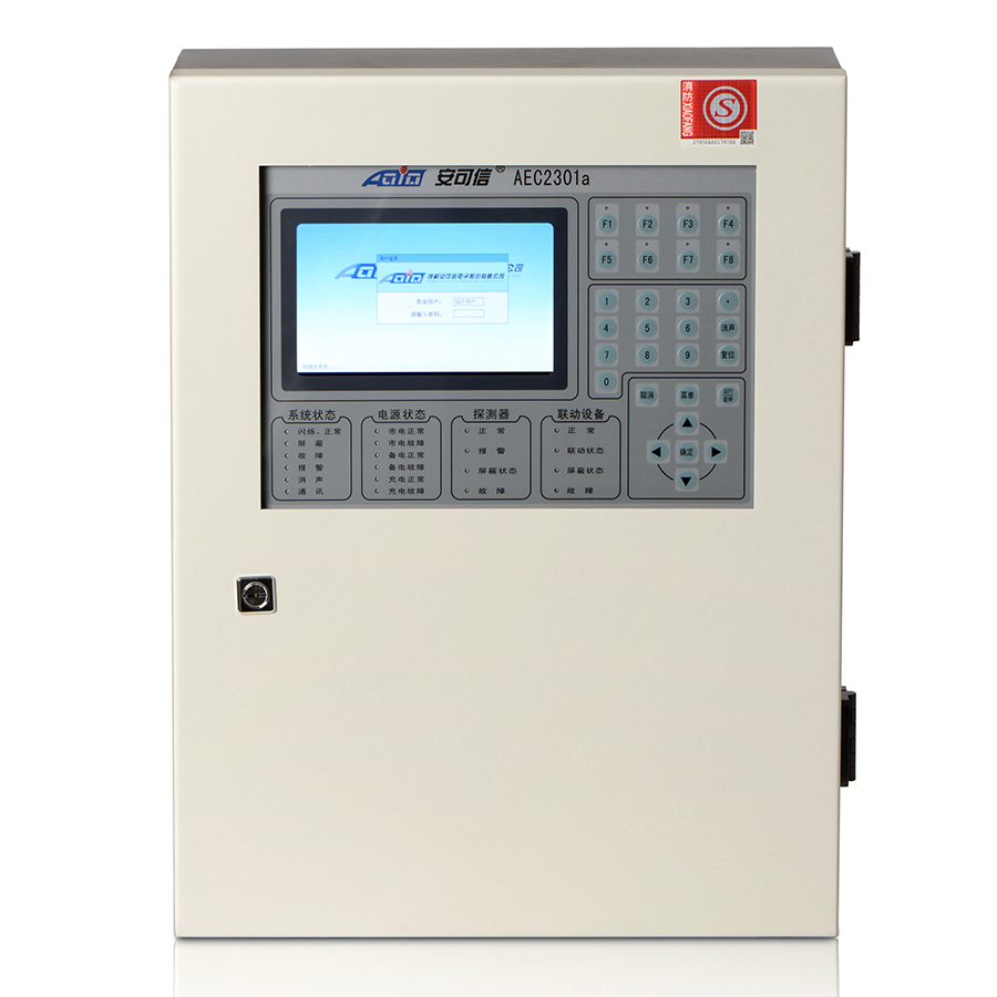
Product detail pictures:

Related Product Guide:
Sticking to the perception of "Creating products of top of the range and earning mates with people today from all over the world", we constantly put the desire of consumers in the first place for Professional China Combustible Gas Detection Controller - AEC2301a A-Bus signal Gas Leak Alarm Controller – Action , The product will supply to all over the world, such as: Jamaica, Macedonia, Myanmar, We supply skilled service, prompt reply, timely delivery, excellent quality and best price to our customers. Satisfaction and good credit to every customer is our priority. We focus on every detail of order processing for customers till they have received safe and sound items with good logistics service and economical cost. Depending on this, our products and solutions are sold very well in the countries in Africa, the Mid-East and Southeast Asia. Adhering to the business philosophy of ??customer first, forge ahead', we sincerely welcome clients from at home and abroad to cooperate with us.
The supplier cooperation attitude is very good, encountered various problems, always willing to cooperate with us, to us as the real God.

